Tuesday, November 8, 2016

Millimeter waves!

Now that my HP 8566B is fixed, I have been able to test the harmonic mixers I made based on the SDMG designs.
I mounted an HSMS-8202 mixer diode on an SMA connector and added a semi-rigid coax feed for the IF (with a tiny wire run through a hole drilled in the SMA connector, and formed into an air-core inductor to act as the diplexer). The LO connects to the SMA connector and RF will be picked up by the SMA center pin (at about 1.5mm height, it's close to a quarter-wave at 47GHz).
I tested at first with the 24GHz Gunn oscillators I have had for a while, but of course I don't need to use an external mixer for these as the 8566B can be convinced to span up to 25GHz in the harmonic locked mode (shift-t). But now I was determined to use the external mixer modes accessed by the shift-U function.
For the next amateur radio band at 47GHz, I had to make a signal source: this is another SMA connector with microwave diode, this time an HSMS286C high frequency schottky. No IF connection needed here, as I'm just multiplying the input frequency. If I wanted to make a transverter, I would have to add an IF input just like the mixer above. I mounted the center pin of the SMA connector in the focal point of a flashlight reflector to act as a parabolic dish antenna. At these frequencies, radio waves act more like light!
To get 47.1GHz out, I had to multiply a lower frequency, and my best bet was the HP8350 sweeper with 83545A plug-in, as this can put out over 22dBm in the 6-12GHz range. I chose to use the 5th harmonic of 9.42GHz, which turns out to be 47.1GHz.
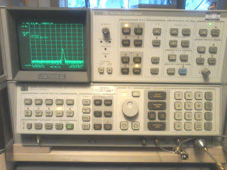
And what do you know, it works! (For the bottom picture, I placed the diode multiplier next to the mixer input at bottom right in the picture, as it was too hard to hold both the flashlight relector and the camera at the same time.) I only sent the signal about a meter, but at 47GHz, that's 157 wavelengths - the equivalent of 25km for the 160m band....

The signal drifts around a bit, as the 8350/83545 sweeper isn't phase-locked, but at least I can pick it up. Next I might try modifying the HP83545A plug-in to act as an amplifier for my HP 8672A synthesised signal generator. If I had a source-locking microwave frequency counter like the EIP575/578 that wouldn't be necessary, but the gods of eBay have not provided me with such a thing.

-mark.

Monday, October 31, 2016

HP8566B repairs


When I first picked up this very nice spectrum analyzer a couple of years ago, I plugged it in to try it out and to my dismay, there was a problem. The high range (2-22GHz) had a couple of spurious signals and very high attenuation of the input signal. I let it sit overnight and tried it again, and happily found that it was working properly. A few weeks ago, the problem returned.

I checked the frequencies of the spurious signals and found they were the product of the 3.3GHz oscillator in the second converter and the LO mixing to give the IF of 321.4MHz. This oscillator isn't supposed to be on when the unit is switched to high range, it's just supposed to mix with the upconverted first IF at 3.621GHz when the unit is switched to low range (0-2.5GHz). The PIN diode switch in the second converter must have been switched incorrectly too, to account for the high attenuation of input signals.

Luckily Keysight (formerly Agilent, before that HP) still has service manuals on their website for some of these older instruments. Unfortunately, the scan quality isn't great on some of the schematic pages, so this is what I get for the circuit that controls the 3.3GHz oscillator and the PIN diode switch:


Some of the component values and designators are unreadable, but I can see that there a couple of test points on the board at the output of the oscillator drive circuit. After moving the spectrum analyzer to a bench where I can stand the units on their sides to access the test points and removing the bottom cover, I test the voltage at the oscillator drive: -7.1V for both high and low ranges. I test the voltage on the PIN diode switch: 19.6V in both ranges. Something is not switching the way it should.

I remove the board from the spec an and test a few things - no shorted transistors, resistors and caps read reasonable values - a puzzle. I try lifting the resistor that connects Q21 to Q4 (R8, I think?) and replace the board in the unit and power it back up. Now the PIN diode switch control is at -9ish volts and the oscillator drive is high (as this signal is emitter current for the oscillator, a low voltage turns the oscillator on). No switching between ranges, but I don't expect it to as I've cut the signal that connects the controller to the second converter.

I probe around a bit more, but don't find anything unusual, so I decide to remove Q21, a plastic-packaged (TO-92) NPN transistor. I test it with the hfe tester in my multimeter and can't get a good reading - perhaps this is the culprit? The C-E junction isn't shorted but it could be conducting enough to turn on Q4. I replace Q21 with a 2N3904 and try again - no luck though. I check the input signal to the card (A6A10, pin 34): 0.7V low, 2.5V high. The high level should be high enough, but is 0.7V too high? It could be turning on Q21 just enough to drive Q4, so I decide to add a 4.7k resistor between Q21's emitter and base - this will increase turn-on voltage at the input to about 1V. Try again: no luck. 

This time, I decide I need to see what's really going on with Q21, so I remove the board and solder a couple of fly wires on the base and collector of Q21. With the board back in, I get 0.4V at the base and 10V at the collector in high range, 0.65V at the base and 0.2V at the collector in low range. The collector voltage supply is 20V, so something is going on to give only 10V when the transistor should be turned off (and 0.4V at the base should not turn on a 2N3904). I decide to pull the capacitor across Q21's C-E junction (C9, as far as I can tell from the schematic). I test it with the multimeter - open circuit, so it shouldn't cause problems. 

Replacing the board and turning on the spec an, I see that the problem has gone away - high and low ranges both work! The collector voltage at Q21 is now 19.7V in high band and 0.2V in low band. C9 must have been acting as a zener - conducting when the voltage reached 10V, but not at the voltage my multimeter tests at. I replace C9 with a surface mount 1206 0.47uF 50V cap and close up the spectrum analyzer (after removing fly wires of course).

Success! I have a fully working 0-22GHz spectrum analyzer again! (Actually, in range-locked mode, it can be pushed over 25GHz...useful for those 24GHz Gunn diode units.)

Friday, May 13, 2016

New scope - TDS 310

So I was browsing randomly for test equipment one day, and saw this on Valuetronix: a Tektronix TDS 310 50MHz 200MSa/s dual-channel digital oscilloscope.

The price was a little hard to believe: $60 (US of course, but the CADUSD exchange rate is recovering after the dip). It did say refurbished on the ad, so I assumed it can't be seriously FUBAR. Out of cal, perhaps, maybe old, dirty, and beat up - but not DOA. I couldn't resist - I had to order the thing. One can never have too much test equipment, you know.

It arrived the other day and I was pleasantly surprised to find a couple of 100MHz x10 probes, a manual on CD, and an extra power cord included. Best of all, when I plugged it in, it passed all self-tests and had no issues displaying the internal calibration signal (you know, that 1kHz 5Vpp square wave). Upon further testing and inspection, this thing looks and acts like a brand new 'scope - it's clean and new-looking, and I couldn't find any problems with the timebase, front end, or measurement accuracy.

Not bad for a basic 'scope - it doesn't have option 14, so no RS-232 or GPIB, the only way to get data out of it is to take a picture of the screen...but that's OK, I have my TDS 510 for that.  (Also the LeCroy 9850AM if I can ever solve the offset cal issue - I suspect the DAC.)

-mark.

Friday, April 29, 2016

Prologix GPIB-USB controller!

I`ve been thinking of getting a GPIB controller for quite a while (since shortly after I started collecting old HP test equipment). I`ve tried to use an IOTech serial GPIB controller, but with very limited success. Finally I saw a used Prologix controller on eBay, so I ordered it. I was delighted to finally be able to use the KE5FX GPIB toolkit to capture images from my HP 8566B...but the excitement was short-lived. The next day, I tried to connect to another instrument, but nothing worked. I tried everything I could think of, but nothing worked. Both the GPIB configurator and EZGPIB reported no communication with the Prologix controller, but the FTDI USB controller inside it was enumerating on the bus, so something had gone disastrously wrong.
I contacted Prologix to ask about the possibility of getting repair parts, but they just told me to send them the defective unit. After they received it, I got an email back:

Hello Mark,

We have received the defective unit. Upon inspection we found that it wasn’t a genuine Prologix unit, but a counterfeit clone manufactured in China.
However, since we want you to be a happy Prologix customer we will send you a genuine replacement at no cost.

So that explains the early failure! I didn't think anyone would counterfeit Prologix controllers (being such a niche market), and they must have gone to considerable lengths to match the external appearance of the genuine units. There were no obvious give-aways that this wasn't the real thing (unlike the ``Noth Frace`` clothing on sale in Kathmandu).

I received the genuine replacement unit about a week ago, and have been putting it through the paces with my 8566B and 8756A. Here`s the HP 8566B with Harmonic lock turned on, set at harmonic 4 (which enables coverage up to 25GHz, yay! I can finally see the output of my 24GHz Gunn oscillators!)
 And a plot from the 8756A of a crappy over-coupled 4.5GHz filter I threw together:
I was hoping that my filter would behave more like this 10GHz waveguide cavity filter (though even it has a few spurious responses just off the passband):

I also learned that if I get an appropriate external harmonic mixer, the 8566B can go well into the millimeter-wave range:

But most of all, I'm happy to finally have a GPIB controller that works! Thanks Prologix!

-mark.
(I was thinking of using `Beware the Attack of the Clones` as a title for this post, but I think that would just be too ugly....)